ESP SURFACE POWER SYSTEM

ZPS-M Wide-Frequency ESP Transformer

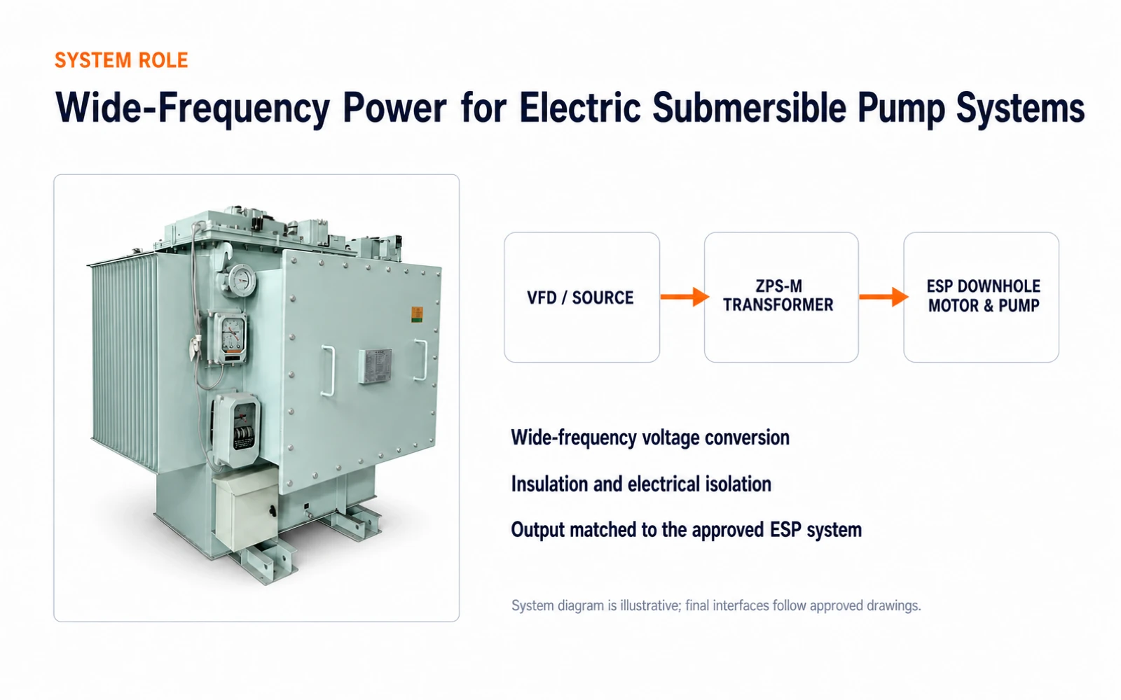
System relationship between the VFD, ZPS-M wide-frequency transformer and downhole ESP motor and pump
The diagram explains system position; final interfaces follow the approved single-line diagram and project drawings.
APPLICATION CONTEXT

The transformer is selected for the complete ESP power chain

At a remote oilfield, offshore production facility or grid-supplied production well, the source feeds switchgear and a VFD. The ZPS-M then provides the project-defined voltage matching, electrical isolation and power transfer before the long cable circuit reaches the downhole motor and pump.

01Remote oilfield stationA diesel generator may be upstream; source variation, grounding and continuous load must be confirmed.
02Offshore production facilityCorrosion, space, vibration, cooling and service access become project inputs.
03Grid-supplied oilfieldVFD output, long cable and ESP motor still have to be evaluated as one system.

The application does not define a fixed model. Rating, ratio, frequency range, insulation, cooling and enclosure follow approved project data.

INDUSTRY SCENE REFERENCES

Where does a wide-frequency ESP transformer operate?

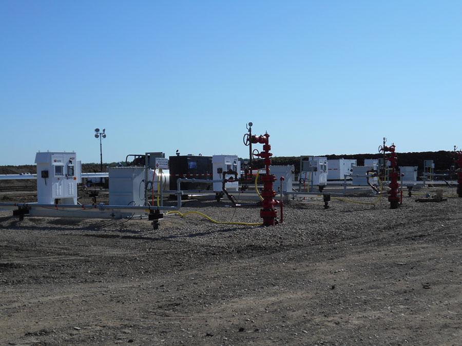
These public internet photographs provide context for real ESP surface-power and offshore electrical environments. The pictured equipment is not manufactured by Shenyang No.4 and is not presented as our project record.

Real multiple-well ESP pad with surface control and power equipment
INDUSTRY CONTEXT · NOT OUR PROJECT RECORDMultiple-well ESP production pad

At a real wellsite, surface controls and power equipment are arranged around several production wellheads. The photograph provides context only; the pictured equipment is not identified as our product.

Source: Canadian Advanced ESP
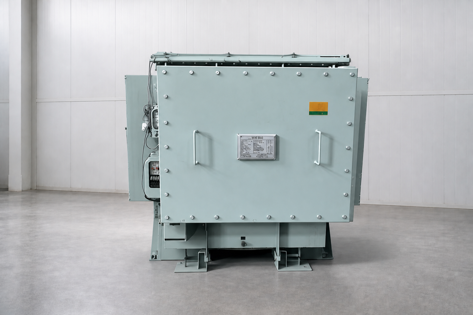
ROLE OF OUR PRODUCT · FRONT VIEWFront view of the Shenyang No.4 ZPS-M wide-frequency ESP transformer

ZPS-M Wide-Frequency Transformer

  1. Input connects to the confirmed VFD output
  2. Transformer provides project-defined matching, isolation and power transfer
  3. Output feeds the downhole ESP motor and pump through the long cable circuit

This section is for local concept review only. Obtain reuse permission or replace these files with factory/customer-authorized field photographs before publication.

Reference Configuration
Subject to Approved Project Data

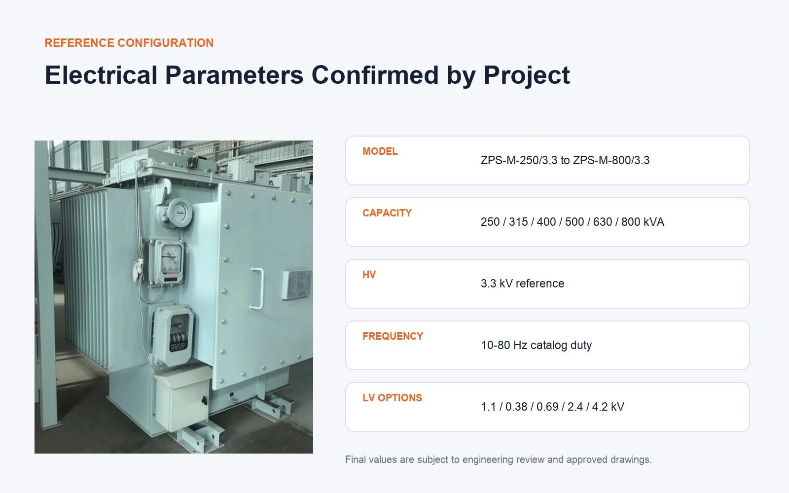
The ZPS-M catalog reference covers 250–800 kVA, 3.3 kV and 10–80 Hz. Low-voltage references include 1.1 / 0.38 / 0.69 / 2.4 / 4.2 kV, selected for the actual system.

These are series reference values, not a substitute for the project specification. Losses, impedance, temperature rise, dimensions and accessories are confirmed before manufacture.

  • Confirm VFD output frequency and continuous load envelope
  • Confirm source, transformer and motor voltage interfaces
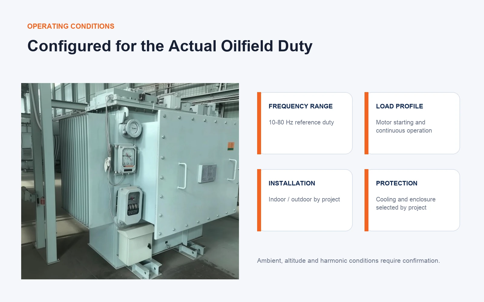
  • Confirm ambient, altitude, harmonics and installation
  • Confirm test scope, documentation and packing requirements
ZPS-M wide-frequency transformer reference electrical configuration
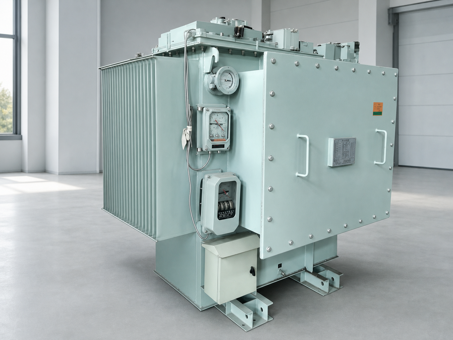
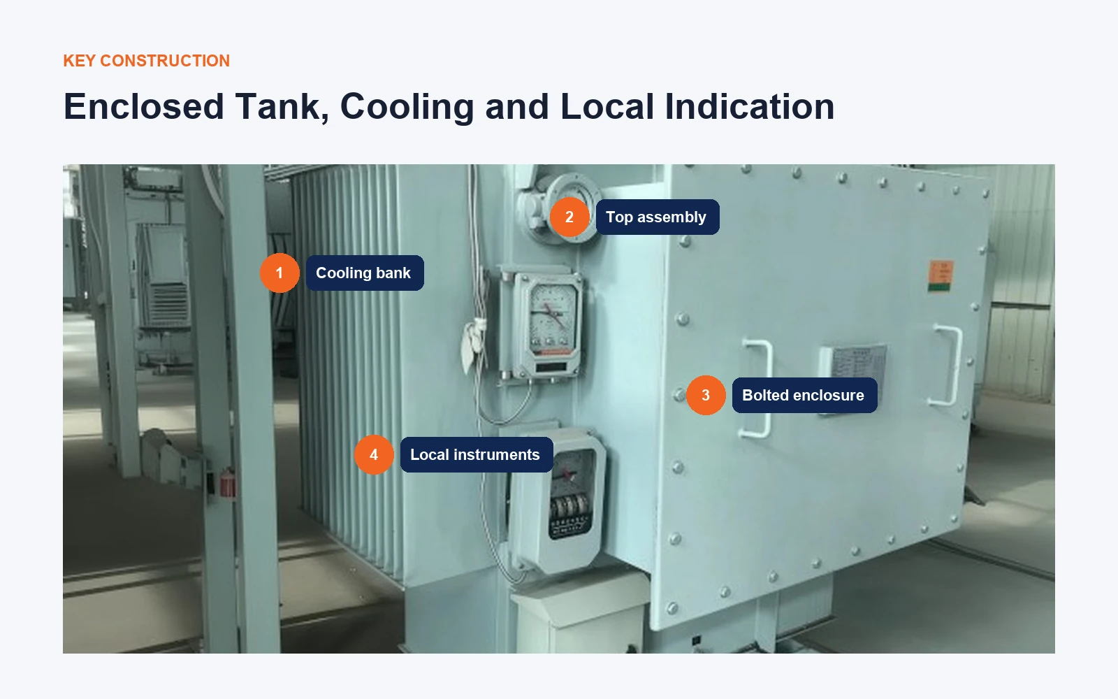
Close view of ZPS-M cooling bank enclosure and local instruments

Visible Construction & Project Confirmation

The close view shows the visible enclosure, cooling bank and local indication arrangement so buyers can review service and interface considerations.

The image represents visible construction on this sample only; final protection, cooling, instruments and accessories follow approved project data.

  • Confirm cooling method and site ventilation
  • Confirm enclosure protection, corrosion and installation space
  • Confirm local indication, monitoring and alarm interfaces
  • Confirm cable direction, terminals and service access
SYSTEM ROLE

From Surface Power to the Downhole ESP Motor

The transformer is selected as part of the complete artificial-lift power chain. A diesel generator may be the offshore or remote-site power source, but the ZPS-M transformer directly interfaces with the approved VFD and ESP motor circuit.

  1. 01Utility or GeneratorConfirm source voltage, frequency, fault level and earthing.
  2. 02Switchgear / VFDConfirm drive output range, waveform, harmonics and continuous duty.
  3. 03ZPS-M TransformerCoordinate ratio, insulation, cooling and electrical interfaces.
  4. 04ESP CableReview cable length, voltage drop, termination and installation.
  5. 05Downhole Motor & PumpMatch motor rating, load curve and operating envelope.
ENGINEERING FOCUS

Why a Standard 50/60 Hz Distribution Transformer Is Not Enough

Selection starts with the operating problem, not with a generic kVA value.

Variable-frequency duty

Flux, losses, temperature rise and continuous loading must be reviewed across the confirmed VFD operating envelope.

Waveform and harmonics

The actual drive output and filtering arrangement affect insulation stress, heating and system coordination.

Long motor-cable circuit

Motor voltage, cable length, voltage drop and downhole operating conditions must be considered together.

Remote and offshore sites

Ambient, altitude, corrosion protection, enclosure, cooling, transport and maintainability are project inputs.

TECHNICAL FAQ

Questions to Resolve Before Quotation

Is the ZPS-M transformer only for diesel-powered drilling platforms?

No. The upstream source may be a utility network or a generator. The transformer is engineered around the VFD output, ESP motor, cable circuit and site duty. Offshore generator operation is one possible application, not the product definition.

Is every ZPS-M unit a step-up transformer?

Not necessarily. “Step-up” should only be used when the approved voltage relationship requires it. Final ratios follow the VFD, motor and system interfaces.

What information is needed for technical selection?

Provide the single-line diagram, VFD make and output data, motor rating, required frequency range, cable data, ambient and installation conditions, cooling and protection requirements, standards, tests and documentation scope.

Are the 250–800 kVA, 3.3 kV and 10–80 Hz values guaranteed for every project?

No. They are catalog series references. Guaranteed values, losses, impedance, temperature rise, dimensions and accessories are defined in the technical agreement and approved drawings.

Send the VFD, motor and cable data.

Our engineering team will review the interface before confirming the transformer configuration.

Request Technical Selection →